
F-5E & F Upper & Lower Cockpit Longeron
Replacement, Special Tools & Installation Training
Download Hard Copy
AS9100D
Technical Documentation For Cockpit Longeron Inspection
T.O. 1F-5E-3 STRUCTURAL REPAIR MANUAL

SINGLE SEAT F-5E
- SECTION III - Pages 3-53 to 3-243
- SECTION III C127 – Sheets 1-31
- SECTION III Paragraph 3-42 to 3-42B
- Page 3-42. Fuselage Structure Repairs
- 3-42A. Fuselage Structure
- 3-42B. RK1001 Installation
2 SEAT F-5F
- SECTION III 3.359 SHEETS 1-40
- SECTION III Pages 3-53 to 3-243
INSPECTION LOCATIONS ON AIRCRAFT
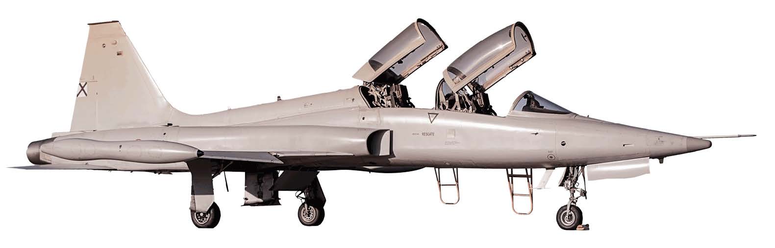
- F-5E Cockpit Longerons Located FS 182.92 to FS284.00
- F-5F Cockpit Longerons Located FS 135.00 to FS 284.00


Addl Reference Data:
TECHNICAL ORDERS (WORKCARDS):
1F-5E-6WC-1 to 6WC-6 & WC-9.
ASIP Inspections
T.O. 1F-5E-6
Lower Cockpit Longeron Repair Program
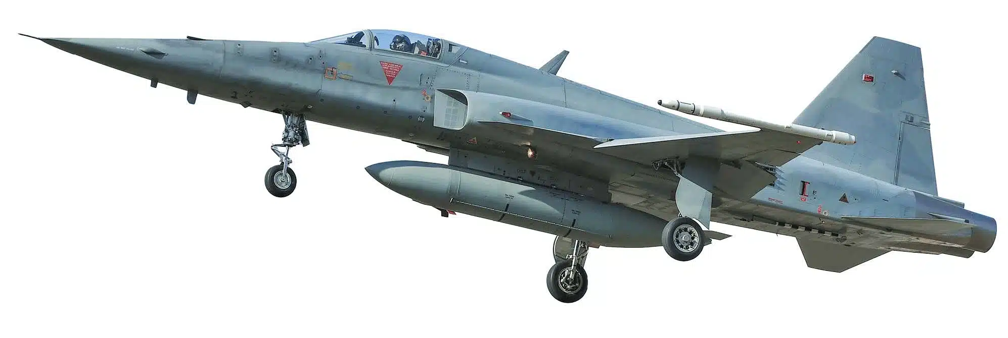
F-5 E and F-5 F Forward Fuselage – location of cockpit longerons


Location of Cockpit Longerons FS 194.00 – FS 284.00


Training Aids for RK1001 Longeron Repair
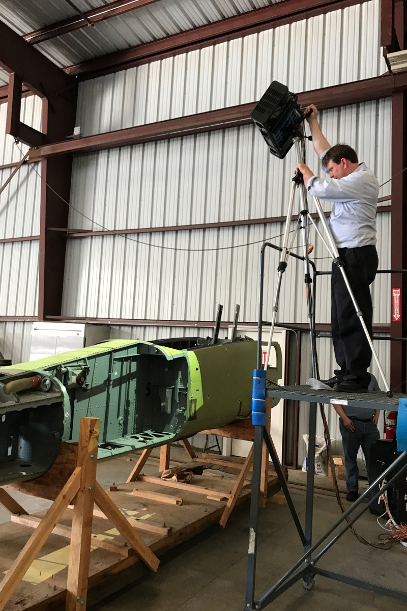
COC uses our Forward Fuselage Section to set up all of the Dimensional Data Recording using our U.S. Patented processes.
All of the dimensions and features of the part are captured with the Photogrammetry equipment, then imported into 3D Surface Software.
This data is then used on the aircraft to be repaired.

Inspect all Formers, Clips, Brackets attached


Inspect lower skins and bulkheads

Colored dots signify different fastener types.

Recommended Additional Inspections
Recommended Additional Inspections while aircraft cockpit is disassembled.
Inspect entire internal Instructure of cockpit including:
- Floor panels
- Rear bulkhead
- Formers
- Brackets
- Clips

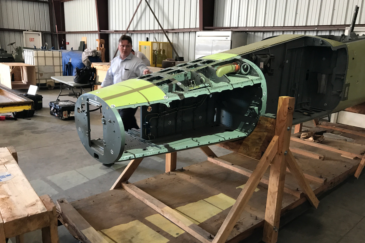
Point Cloud data is collected into 3D surface model
All of the 3D dimensions of the aero-structure to tolerances of less than 0.005”

Photogrammetry session with F-5
Aircraft fuselage is scanned with our cameras.
Data is collected in 3D Surface Software.

From Scanned part to 3D Surface Model


Upper Cockpit Longerons modeled in CAD are positioned ‘as installed into F-5 airframe


Upper Cockpit Longerons modeled in CAD are positioned ‘as installed into F-5 airframe
With fuselage stations identified.

Video Projection directly on to the work area
All of the Work Instructions are displayed on the aircraft aerostructure, eliminating the need to refer to Work Cards, T.O.s etc.

Thank You
EXPERIENCE - OVER 5 DECADES YEARS SUPPORTING LEGACY AIRCRAFT
CUSTOMER SERVICE - OVER 50 YEARS SUPPORTING THE SAME CUSTOMERS
TRUST - ABOVE ALL, WE ALWAYS DO THE RIGHT THING